• Can't post after logging to the forum for the first time... Try Again - If you can't post in the forum, sign out of both the membership site and the forum and log in again. Make sure your COG membership is active and your browser allow cookies. If you still can't post, contact the COG IT guy at IT@Concours.org.
  • IF YOU GET 404 ERROR: This may be due to using a link in a post from prior to the web migration. Content was brought over from the old forum as is, but the links may be in error. If the link contains "cog-online.org" it is an old link and will not work.

Mccruise controller with rostra?

hammerash

Member
Member
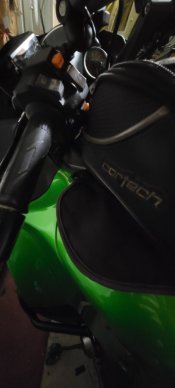
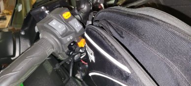
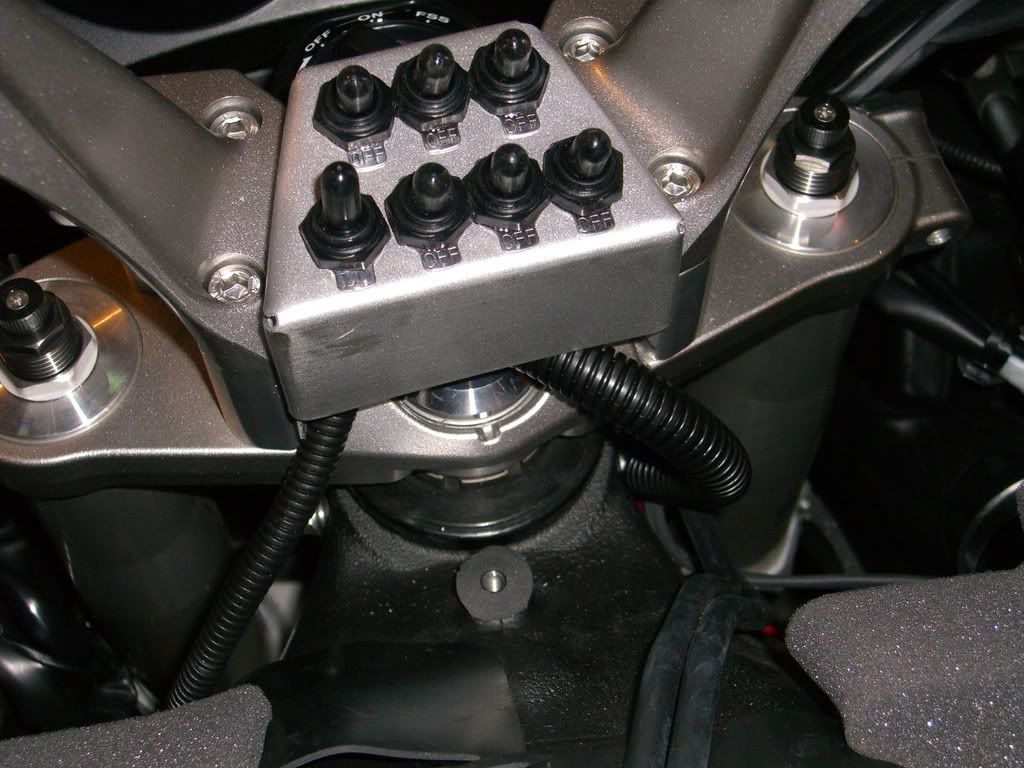
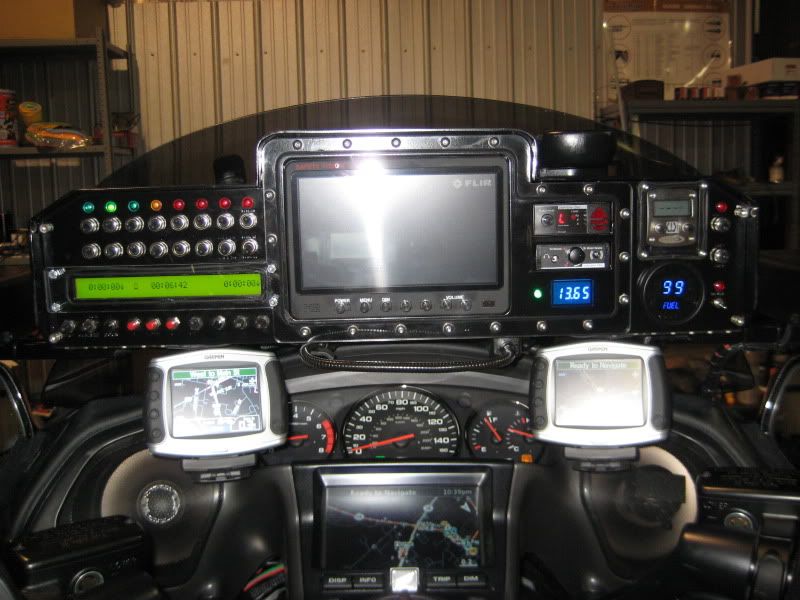
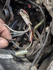
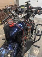
So considering cruise. I like the cost of Rostra, but don't particularly like controller. The one with 2 lights I guess not bad. But it is gray and have to take apart to try to waterproof. Mccruise has slimline controller. Need 10mm on handlebar, which Concours doesn't have and only way to get it would be move grip and switchblock over to left to make room. This would be clean looking install. But hate to move everything as would not be symmetric with throttle side. Screenshot_20230516_161226_Chrome.jpg

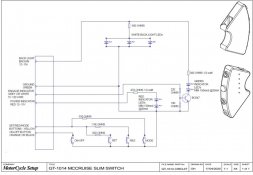
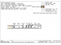
They mention that they are making brackets to mount underneath switchblock like thisScreenshot_20230516_164124_Chrome.jpg
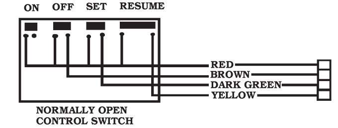
Not sure if they have one for concours. I just sent them messsge to see if they do. Think it would be possible to use this switch, or their standard switch, with Rostra unit? Have to figure out the wiring but would think feasible? It contains On/off switch, set/accel switch, resume/decel switch, and a light. Thought maybe someone with experience with these may have insight.
 
Do they sell yhem separately without yhe main unit? U could always paint the rostra controller housing to match yhe switch gear..
 
Yes they sell them. The slimline switch is $61. I looked at install instructions for switch and the unit. Unfortunately, since it is more plug and play and comes with the wires in a plug that connects to the mccruise computer, I am unable to tell which wires go where.

Hard to paint Rostra given it has writing on it. I guess could mask off writing in rectangles and paint. But I think the skimline controller is much nicer looking installation.

I moved clutch perch as far as possible to right, towards the handle holder . But given the master cylinder bleed screw bulges, it won't go flush, so only about 4mm space between switchblock and clutch perch. Need 10mm. Could you remove handle and put a small spacer between it and handle holder? Those are way parts described on partszilla.
 
Last edited:
I thought maybe they would not want to give me the details of switch, but I was wrong. They sent a lot of info. Knowing whether this could be used with Rostra unit is beyond my skill set. Any Electrical Engineers? Here is their reply as well as diagrams.

Hi Bill,

I have attached the actual circuit for the control switch, see GT-1014-CIRCUIT MCCruise Switch.pdf. This circuit applies to our current standard and slim switches.

I have also attached the ‘equivalent’ circuit, see MCS820 Circuit Diagram, which is basically how it presents to the outside world and was the actual circuit used in our switches up until a few years ago.

The new circuit was done a few years ago to allow more flexibility with the indicator light illumination.

We do still have some stock of our original control switch which is made up from individual parts (housing, keypad and circuit board are all separate parts). With this older switch, it would be possible to mofify the PCB and resistors etc fitted to the PCB.

Our current switches, both the ‘standard’ switch and the new slim switch are fully potted and cannot be disassembled or repaired.

The normal inputs to the switch wires are:

Green = ground

Yellow = this is a variable voltage, the SET, RES and MODE (the indicator light is a button as well) are resistor encoded pulling to ground.

Brown = 12V supply to the back light a power source for the green indicator light.

Orange or black = signal line to the Power (ON-OFF) button, the switch pulls this to ground when pressed.

Grey or White = 5V current limited supply to switch the green indicator light on. The cruise computer has a current limiting resistor built into this circuit, hence the 0 ohm link on the switch PCB. This could be supplied from a 12V source with a suitable current limiting resistor fitted to the wire.

Red = 12V supply to the red indicator light. Our cruise has the ability to apply a PWM supply to this input so we can adjust the brightness of the red indicator LED. We use this in combination with the green indicator LED to balance the resulting colour when red and green are both on (produces anything from dark orange through yellow to greenish-yellow) depending on the PWM (Pulse Width Modulation) percentage, so the more we reduce the brightness of the red LED, the less red/more green the colour becomes.

Let me know if you need any more detail.
 

Attachments

  • Screenshot_20230517_105550_Microsoft 365 (Office).jpg
    Screenshot_20230517_105550_Microsoft 365 (Office).jpg
    106.3 KB · Views: 45
  • Screenshot_20230517_105451_Microsoft 365 (Office).jpg
    Screenshot_20230517_105451_Microsoft 365 (Office).jpg
    115.3 KB · Views: 48
I'm no electrical engineer, but I think it won't work. The Rostra switch is a very basic set of momentary switches using different lines, where as the McCruise switch sends the "Set" signal and the "Resume" signal down the same wire but with different voltages. I'm not saying the McCruise switch couldn't be made to work if you opened it up and rewired the inside, but I'm assuming you do not want to do that?
Someone else didn't like the Rostra switch and just purchased a couple of normally open momentary switches (maybe 3) IIRC (?)he wired it so it would be on all the time so he skipped the on/off switches, he just went with a SET and a RESUME switch and no labels. I'll see if I can find a link to his set up.
 
Last edited:
Yeah, this switch looks complicated. But I do Like the way it looks. Almost OEM appearing.

That bike looks like the cockpit of a plane! That is a lot of switches.
 
I drew up a mount for my Rostra panel in CAD. I've already 3D printed it and I plan on installing it this weekend. I'll let you all know how it goes.
 
please do. some pictures would be great. I would love to see more ways that guys have installed switches. trying to find old threads.

so for Rostra vs McCruise install, this is what currently looks like

Rostra 250-1223 main unit $260
Rostra 250-3592 switch with engaged light $60
Recoy LD-12P relay from Murph's (2) $22
total $342

McCruise $897
shipping $68
total $965

Huge difference. am I missing any others costs? that is not with slimline switch on McCruise. separately, the switches are same price but the kits come with standard switch. Don't know if they will swap out for it or if have to pay extra?
 
....am I missing any others costs?
Nothing major that I can think of. Maybe some cable covering, heat shrink tubing, RTV sealant, Posi-Lock connectors. Perhaps some labels or tags for the wiring?. Most just want to get the job done and get it working...but a few labels on the wires will be so helpful 2-3 years down the road when either you or someone else has to go in there for something else, or troubleshooting if it quits working.
 
Last edited:
I drew up a mount for my Rostra panel in CAD. I've already 3D printed it and I plan on installing it this weekend. I'll let you all know how it goes.
I have a Rostra sitting here in a box, been too tied up to install and last I looked was also seeking a nice mount.

Please, if you can, share your part pics. Do you have your own 3D printer?

Wayne, Carol & Blue(without electronic cruise)
 
clutch-side-mount.png


I do have my own 3d printer. It doesn't replace the clutch clamp, but sits on top. Uses 10mm longer bolts.
 
Hard to paint Rostra given it has writing on it. I guess could mask off writing in rectangles and paint. But I think the skimline controller is much nicer looking installation.
The Rostra comes apart, and the only writing on the housing is for the ON and ENGAGED leds. The other silkscreening is on the buttons themselves.
 
Ok. I was rotating 180 degrees. One could be made to put it below switchblock. Have to tilt opposite of what that one is. I think that's where I would want it. Keep hand on grip and use thumb to push buttons. But eager to see your finished product installed.
 
Ok. I was rotating 180 degrees. One could be made to put it below switchblock. Have to tilt opposite of what that one is. I think that's where I would want it. Keep hand on grip and use thumb to push buttons.
If you have, or plan on getting, a large tank bag (I feel naked for some reason without mine 😨😱😵‍💫 ) be sure to consider full lock left turn clearance if you mount the Rostra switch underneath the switch-block. That's why I went above the switch-block with mine. (I was going to paint that aluminum mount black ["someday"]). Yes, I do have to remove my hand from the left side to actuate the switch but it hasn't been a problem. I may ("someday") make a better mount so it's further to the left over the very end of the switch-block so I can get it with the thumb. However, I'm frequently removing my left hand from the grip for adjusting my visor, Sena controls, scratching my nose, changing the temp in my heated gear, getting a drink of water, changing the grip heat setting, poking at the Zumo GPS, getting a piece of hard candy out of my tank bag...so that's kinda why "someday" may never come for me.
I recommend just getting it installed and working the easiest way you can, then after you've used it a while you'll know how to go back and make it perfect. Too many have purchased theirs and then never installed it (I'm sure Murph was good with that when he sold them 😛 ), they never got to enjoy the payback of even a less than perfect install.
 
Last edited:
Hadn't thought of tank bag issue. I always rode with one. But that was my ninja with no luggage. Always pain taking it off to fuel up as have to disconnect 3 push connectors. Not sure if be using it now that I have saddlebags and topcase. I'll have to put it on and see what kind of clearance I have in case I do start using it.
 
So I tried my tankbag. I am shocked that there is no way I can use it! I use it on my ninja without any problem. But it is way too big for Concours. When I was getting ready to fly to pick up my Connie last month, I asked seller if tank bag was included. He hadn't thought about it but said I could have it. It is smaller one. Good thing I didn't do as I planned and take my bag for trip home as it would have been nearly impossible to ride with it. First 2 are my old tank bag and last 2 are bag that previous owner gave me. Even it hits at full lock. So yeah, need to consider this when mounting cruise control buttons.
 

Attachments

  • 20230519_220545.jpg
    20230519_220545.jpg
    46.2 KB · Views: 53
  • 20230519_220601.jpg
    20230519_220601.jpg
    69 KB · Views: 54
  • 20230519_220055.jpg
    20230519_220055.jpg
    137.5 KB · Views: 57
  • 20230519_220140.jpg
    20230519_220140.jpg
    75.2 KB · Views: 57
So I tried my tankbag. I am shocked that there is no way I can use it!


I wouldn't be so sure of that, just touching the tank bag is not a deal killer in itself. Parking lot jostling and police style slow speed courses are the only time you are going to be full lock and if your hand can stay on the bar (no doubt with some flexing of the tank bag) you should be good to go.

I have a large tank bag and it barely touches the bar at full lock. Mine is on a tank ring mount instead of straps. I spent more on my tank bag and electrified mount than I did on the Rostra. I do not regret it, although it hurt my wallet at the time. Mine can be adjusted (not constantly, but it can be moved if the first install is problematic) so I moved it back until the horn button didn't get pressed at full lock left. Full lock right, one would need to be careful with a cramp buster throttle assist which could be dangerous if contact with the tank bag is made.

For yours, I was just worried that an under bar mount might break (plastic 3D printer type) if you didn't have it far enough towards the front of the bike so that the bar would hit the tank bag first.
 
Last edited:
Originally I had considered putting mine on throttle side, but I realized yhe tank bag might be a problem. So I went up and left. I did downsize to a narrower tank bag. Tourmaster 14liter with the expansion zipper. No problems with full turn lock, but i do have helibars.
 

Attachments

  • 16846156322967266708282569665689.jpg
    16846156322967266708282569665689.jpg
    99.4 KB · Views: 56
What is that just to left of Rostra controller? Looks like the light sensor for my headlight modulator on my ninja? Debating on one for Connie. Gets you noticed.

And how is that zumo mounted? I was looking for some way above gauges but didn't see option.

I need to hit a meet to get ideas what you all have done to your bikes!
 
Good eye! Photo eye for the headlight modulator. I've resisted going to led headlights cuz my modulating headlights work. And have saved my bacon many times. Kissing makes one for led. The regular headlight modulator isn't compatible with the led.

Dash shelf is something that's hard to find. Not being made any longer. Tried talking Larry buck into making them, as he use to make them for the c10. Alas he said no. Can't remember which cog member I got it from, bud perhaps. I'll have to check old messages. Try searching ebay for police dashes for c14. I still have to install the new and improved windscreen bracket, so I suppose I could take it off and get dimensions for it...?
 
It is a pretty simple shelf really. It is just the shelf with 3 bent tabs that go down the front of the bike and then you drill holes in the plastic and push in the rubber well nuts. I made support bars that go up under the front (calling the side closest to rider the "front" here) to make it more rigid and slotted a lamp stem to put over the front because I just saw the front of that shelf slicing into my feet when I flew over the bars in an accident. I covered the
lamp stem with a piece of black fuel line.

https://fartymarty.smugmug.com/Motorcycles/C14-Dash-Shelf/n-H7d8LF

hMMM...WE GOT OFF TOPIC HERE....AHHH...I KNOW..I'LL TIE IT TOGETHER WITH A PHOTO TO KEEP THE MOD HAPPY (y) 🤞

Below is a photo of my Rostra "engaged" light (but is also shows the attach point for the dash shelf support {wink wink nudge nudge})
i-9DQQcF2-M.jpg
 
Last edited:
Looks pretty good. After thinking about it and seeing the interference with tank bag, maybe just above KACT button would be good for me. I don't see using that button a whole lot so if block it a bit shouldn't be issue. Then I noticed you don't have KTRC or KACT buttons?? And looks like the openings were never cut out? Or did real good job filling them in. What's up with that?
 
Re-did the model so that the bracket behind the switch panel is the same size as the panel. Now to re-print and try new settings to get a smoother finish.
 
Mine is a 2010. They were optional that year.

I could be wrong (I frequently are {<--SWIDT?}) but I think the 2010 without ABS et. al., is the most rare C14 and maybe the most coveted model in 25-40 years when the it starts becoming one of the museum bike collectables.

The rarest part? ...and maybe the hardest to find in the future? : 43095-0501
===================================================
Ok, back on topic...McCruise control on a Rostra

Well as I pointed out, I think that is a bad idea unless the McCruise control is easily disassembled for modification. If the control that comes with the Rostra is out of the question for you then I think the two waterproof switch option I referenced earlier from Stavee would be the way to go.
Although I have no first hand knowledge of the McCruise hardware, it is my understanding that it excels in three areas; 1) the control switch which is seemingly low profile; 2) The wiring which I think is all pre-connectored so it is, or almost is, plug and play (,--I could be wrong about this); 3) the throttle control hardware connection. I have usually have little problem with wiring, so for me the hardware connection to the throttle was my biggest problem, and IMO the McCruise proprietary hardware is the most valuable piece of their kit. I eventually came up with a nice sturdy (but very ugly) solution that I was happy with, but all the maneuvering I did caused damage to my main wiring harness that I had to repair. I think if I wasn't being rushed by an install deadline of my own making and the 96 degree heat in my work area that I wouldn't have booger-ed up the main harness as I did. Plenty of others installs did not have a problem in this area.

This is one of the best tools available for the wiring that I know of: https://www.pbase.com/fredharmon/image/145443506

There are two switch types for the Rostra, normally open and normally closed. I think (but not 100% sure) the normally closed types are the automotive stalk types. Ours are the normally open type. I haven't found a complete circuit drawing for inside the switch but I think the one available online is good enough to get the idea. It doesn't show the wiring (or rather the circuit board paths) for the illumination LEDs or the power on LED or, if so equipped, engaged LED. It also doesn't give a complete idea of how the "On" switch works.

Wiring%20for%20cruise%20switch.jpg
 
Last edited:
thanks, Fartymarty. I think McCruise said their switch is not serviceable. At least the new ones. The older switch was serviceable, but they did not have a slimline version back then. So I doubt it could be modified internally. Just wanted to see how rostra switch wired. We need to find a way to get a slimline like switch that will work with Rostra! Think there would be interest, or is it just me, LOL.

So the hardware mounting caused damage to wiring and not splicing the the wires? Did something rub the wires?

I nearly purchased Mattchewn's old bike (green 2015) last April. I actually ended up speaking to him-the new owner put me in contact with him. He said something to the effect that there was a problem with Rostra initially with not being smooth, but once the mounting was figured out it works great. He had an previous Concours so I think he meant he improved setup on the 2015. I don't know if he meant location of unit? That bike had on left side near coolant overflow bottle. Or the position of connection to throttle? I assume further away is better as not as abrupt (a given amount of cable movement gives less throttle movement). I read mention of an extension on throttle, but when search for that topic the links are broken. Or if he meant something else?

wiring doesn't scare me. On my ZX-9R, I have an alarm that required cutting main ignition wire. Wired in alarm with factory bullet connectors with the clear covers, so I can remove alarm and connect wire back together and be just like original. I also put in a gear indicator. Required tapping into the tach, VSS, Neutral signal. I did those without cutting any wires by pulling the pins from the plastic connector and soldering in extra wires back there and reinserting pin back into plastic. Very clean! So the hardware part of install is tough part for me. Getting Best location for unit, fabricating a mount, etc.
 
So the hardware mounting caused damage to wiring and not splicing the the wires? Did something rub the wires?

Yes, I had used a grinder to grind a clearance arc in the mounting strap and then failed to properly round the edges to avoid chaffing as I maneuvered it into a position I liked (several tries). Increasing haste (It was already several days of install because I started out slow in the heat), and discomfort caused carelessness (hot in my garage) on my part was the problem.

Brian (B.D.F.) preferred the cable link and I preferred the ball chain link. My thought was that if either got caught on something and held the throttle open, I felt I could overpower the ball chain and break it with the OEM positive return cable on the throttle.
I can't recall Brian's reasoning, and we can't ask him (RIP), but it might have been that he thought the cable would be less likely to get caught on something than the ball chain since it was stiffer. Brian mounted his actuator unit on the left as you can see in his photos, but that location just looked too hot to me, so I put mine up high under the right side top cover where my C14 originally had the vapor canister which I removed. My actuator is just nested in some old computer mouse pad material and bungied/zip tied in place.

Link to my install notes including extension arm for throttle.

I can no longer find a link to Brian's instructions. They used to be on Murph's Kits website but I guess he pulled them when he quit selling Rostras?
I had downloaded what I think are all of Brian's original photos over 10 years ago, but I think there was text as well and I don't see that in my files.

Brian's Photos---->https://fartymarty.smugmug.com/Brians-BDF-Rostra-Install-Photos/n-ZbXwLg
 
Last edited:
Thx. I have Brian's instructions with text. Can't remember how I got them, maybe just googled? I think maybe the link on murph's site is bad?
 
Thought I would chime in as I spent a good part of the day troubleshooting mine. It died this past weekend. I figured it was a loose wire. It was installed by PO so I didnt know much about it other than its worked well for 50k I have put on the bike.
I thought it had power because when I turned it in a light came on so I was chasing the brake, clutch and speed sensor stuff. Printed Brians instructions but he didnt use those. I was ready to give up when I discovered everything connected to aux fuse box was out. Jumped the trigger wire and TWO lights came on the keypad. In 6 years with this bike you would think I would know that.
So now I knew it wasnt being triggered. Turned out it was a bad connection coming off the power plug. Had I know would have been a 30 minute job.
 

Attachments

  • PXL_20230605_183941803.jpg
    PXL_20230605_183941803.jpg
    145.8 KB · Views: 47
  • PXL_20230605_183928673.jpg
    PXL_20230605_183928673.jpg
    190.8 KB · Views: 43
On the keypad. My pad is the same one used on the older audiovox units. Its on the left side mounted low . I use a very large magnetic tank bag. I just slide it back for low speed maneuvering.

PS. I can email Brians instructions if needed.
 
On the keypad. My pad is the same one used on the older audiovox units. Its on the left side mounted low . I use a very large magnetic tank bag. I just slide it back for low speed maneuvering.

PS. I can email Brians instructions if needed.
Thx, but I do have them. At least a web link. I should probably print them out.
 
Top